
Thursday, August 13, 2015
Throttle Position Switch
Throttle Position Switch type sensors are very basic and are rarely used on the modern engine. They detect when the throttle is at full throttle or at idle. This particular throttle switch is a two position sensor and has only three pin outs. Another type is a three position sensor making it a four pin out switch, this gives the driver that extra gradual throttle response for better economy. These are both also adjustable, to ensure optimum operation and also good economy.
 From zero to fifteen degrees, the ohm reading is at 0.5ohm. At fifteen degrees, the resistance shoots to an overload reading (O.L.). As the angle increases, up to seventyfive degrees resistance stays in overload (O.L.). From seventyfive degrees the resistance is back in range, at 0.5ohm.
Throttle Position Sensor
The type of TPS sensor we use here is called a Linear throttle position sensor or Pontentiometer type sensor. Potentiometer type sensors hold a variable resistor with a slide contact inside of them. As you push in the accelerator and the throttle butterfly moves, the contact changes its position on the variable resistor. As the throttle position changes the output voltage from the sensor changes. As the throttle opens (throttle position angle increases) the resistance is decreased, thus increasing the output voltage from the sensor:
15` - voltage is at 1.4v
30` - 2.1v
45` - 2.6v
60` - 3.1v
75` - 3.6v
90` - 4.7v
Idle puts out a low voltage (the least voltage) and this is how it is recognised. Usually about 0.4 - 100mV.

15` - voltage is at 1.4v
30` - 2.1v
45` - 2.6v
60` - 3.1v
75` - 3.6v
90` - 4.7v
Idle puts out a low voltage (the least voltage) and this is how it is recognised. Usually about 0.4 - 100mV.

Wednesday, April 20, 2011
Circuit Board #3
Oxygen sensor tester
This circuit basically tells you how your O2 sensor is functioning. Whether or not it is receiving the right signals for the ever-changing air/fuel ratio mixture.
It has an input from the sensor that varies, and depending on the input voltage given from the sensor, it uses operational amplifiers to give various signals. We use LEDs to display the different outcomes as a result of the varied input signal from the sensor (O2 sensor). Red LED displays a rich Fuel/Air ratio mixture, Green displays a lean mixture and yellow is Lambda1 (correct ratio mixture).

When the car is running lean the oxygen sensor puts out a very low voltage. This would make the input at pin12 lower than the 0.23v at pin13 and in turn allows pin14 to ground out through pin11. The green LED will be on.
When the car is running rich the oxygen sensor produces a higher voltage. In this case, it will be higher than 0.63v at pin6. The red LED will then be grounded through pin11, and be turned on.
To find;
R2 = [Vs - Vd (led1) - Vd (d2)] / A
= (12v - 1.8v -0.7v) / 9.5mA (minimum current needed to flow through the LEDs)
= 9.5v / 0.0095A
= 1000ohm
= 1k/ohm resistor
R3 = [Vs - Vd (led5) - Vd (d2) - Vd (d4)] / A
= (12v - 1.8v - 0.7v - 0.7v) / 9.5mA
= 8.8v / 0.0095A
= 926.315ohm
= 1k/ohm resistor
R4 = [Vs - Vd (led6) - Vd (d2)] / A
Components:
= (12v - 1.8v -0.7v) / 9.5mA
= 9.5v / 0.0095A
= 1000ohm
= 1k/ohm resistor
R5 = [Vs - Vd (d2) - Vz (zener diode)] / A
= (12v - 0.7v - 9.1v) / 5.6mA (current needed flow through the zener diode)
= 2.2v / 0.0056A
= 392.857ohm
= 390ohm resistor
R6 = 10k/ohm
= 10000ohm (as given)
To find R7 & R8, we must firstly find the current in the circuit they are on, so;
Voltage drop across R6 = the voltage going IN (Vin) minus the voltage coming OUT (Vout);
= 9.1v (Vin) - 0.63v (Vout)
= 8.47v
Now we divide the voltage drop into the resistance as ohms laws requires and;
Current across R6 = 8.47v / 10000ohm
= 0.000847A
= 0.847mA
This determines current across R7 & R8, and from here we can calculate their resistance values by dividing their voltage drops (Vin - Vout) into the current. So;
R7 = Vd (Vin - Vout) / A
= (0.23v - 0v) / 0.847mA
= 0.23v / 0.000847A
= 271.546ohm
= 270ohm resistor
R8 = Vd (Vin - Vout) / A
= (0.63v - 0.23v) / 0.847mA
= 0.4v / 0.000847A
= 472.25ohm
= 470ohm resistor
Components needed:
1 x 14 pin out op-amp
3 x 1N4001 diodes
3 x LEDs (red, yellow and green)
1 x Zener diode (9.1v)
3 x 1 k/ohm resistors
1 x 10 k/ohm resistor
1 x 390 ohm resistor
1 x 470 ohm resistor
1 x 270 ohm resistor
2 x 0.1 uF capacitor
Below is a couple links to videos of my oxygen sensor tester in operation. You can see how, as the throttle opens it gives a rich signal and as the throttle is released a lean signal is given.
Below is a couple links to videos of my oxygen sensor tester in operation. You can see how, as the throttle opens it gives a rich signal and as the throttle is released a lean signal is given.
http://www.youtube.com/watch?v=X8-9xLdYL5s
 |
| The oxygen sensor tester displaying a rich mixture |
 |
| The oxygen sensor tester displaying a lean mixture |
Under normal conditions the tester will fluctuate between the rich and lean mixture signalling LEDs. This is because of the ECU receiving these same signals and is adjusting the amount of fuel added to the air-fuel mixture constantly. This in turn keeps the emissions relativly close to Lambda1 which is good.
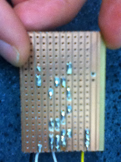
A fault in the circuit is giving a zero volt (0v) reading before and after each LED.
This means that the fault is somewhere before all the LEDs. Back tracking and testing components reveals 12v is available before the diode D2. Although after the diode available voltage is zero.
At first glance, I could not visually see anything abnormal. But slighty playing with diode revealed an open circuit. Cracks between the solder and the track had stopped current from flowing in through the first component to the rest of the circuit.
Repairing this gives us correct voltage drops across the LEDs, and the rest of the circuit again.
To do this experiment again would allow me to be a bit more delicate with my soldering to prevent shorts and/or open circuits.
Circuit Board #2
Circuit Board #2
Construct a circuit, that simulates a Voltage Regulator
This circuit represents a 5V output from an ECU used to signal the fuel injectors.
This circuit represents a 5V output from an ECU used to signal the fuel injectors.

To calculate resistance needed;
[ Vs - LEDv ] / I
= [ 5 - 1.7 ] / 0.02
= 3.3 / 0.02
= 165 ohm
Thus establishing the a 180 ohm resistor used as R1. If R2 = 240 ohm (data sheet specification) then;
Vout = Vref (1 + R3 / R2)
= 5 = 1.25 (1 + R3 / R2)
= 5 / 1.25 = 1.25 / 1.25 (1 + R3 / R2)
= 4 - 1 = R3 / R2
= 3 = R3 / R2
Meaning R3 is 3 x R2;
R2 x 3 = R3
= 240 x 3 = 720
So R1 = 180 ohm, R2 = 270 ohm and R3 = 820 ohm
Components:
1x LM317 Voltage Regulator
1x LED
2x 1N4007 diodes
1x Zener diode
2x 1uF capacitors
1x 180 ohm resistor
1x 270 ohm resistor
1x 820 ohm resistor


Again using Lochmaster to create a circuit board design. Gives a great range of components.
If u hadn't noticed (and I didn't) the underneath of D4 (the black diode above) has not been cut, therefor it is being shorted, and defeats the purpose of even having one. At first my voltage regulator was not working, but Scott was quick to help and point this out.
After a long fluff around I got the board to produce a just less than average result;
Regulated Voltage = 5.9V

Voltage drop readings;
Regulator:
Input to Output = 6V
Input to Adjust = 7.3V
Adjust to Output = 1.25V
D13 = 0V
D12 = 6.05V
D15 (Zener) = 12V
LED = 4.3V
R1 = 2V
R2 = 1.25V
R3 = 4.66V
C16 = 5.9V
C15 = 12V
The reason for less than perfect result i suspect, is because of a resistor being too high. Either R2 or R3. Never the less, the concept is present.
Circuit Board #1 (Injector Circuit)
Circuit Board #1
Construct a circuit, simulating an injector circuit
This board simulates two 5V signals sent to two individual fuel injectors (LEDs are used for simulation purposes) in a circuit. We use a function generator to produce the ECU simulating pulse of 5 volts through the base of the transistors.
This board simulates two 5V signals sent to two individual fuel injectors (LEDs are used for simulation purposes) in a circuit. We use a function generator to produce the ECU simulating pulse of 5 volts through the base of the transistors.
 |
| Injector Circuit wiring diagram |
To Calculate resistance needed;
Datasheet info:
BC547:
max Ic = 100mA (0.1A) & Ib = 5mA (.005A)
min Ic = 10mA (0.01A) & Ib = 0.5mA (.0005A)
This also gives us Beta (B). Ic / Ib = B:
0.1(100mA) / 0.005(5mA) = 20
0.01(10mA) / 0.0005(0.5mA) = 20
Datasheet info:
BC547:
max Ic = 100mA (0.1A) & Ib = 5mA (.005A)
min Ic = 10mA (0.01A) & Ib = 0.5mA (.0005A)
This also gives us Beta (B). Ic / Ib = B:
0.1(100mA) / 0.005(5mA) = 20
0.01(10mA) / 0.0005(0.5mA) = 20
Datasheets are nessesary to calculate the values of the resistors (r13, r14, r15 & r16). They indicate that the LEDs needs a minimum of 20mA (0.02A) in its circuit to operate. The Collector side of the Transistor has a minimum of 10mA and a maximum constant current rating of 100mA (0.1A).
So iv decided the current needs to be safely between 20mA (to enable the LED to operate) and 100mA. 60mA (0.060A) is good.
Therefor;
B (beta) = 20
Ic = 60mA
And if, Ib = Ic / B
= 0.060A / 20
= 0.003A
Then that would mean,
Ib = 3mA
Components:
2x NPN type transistors
2x 1 k/ohm resistors
2x 470 ohm resistors
2x LEDs
Using Lochmaster demo allows us to create a base design to work with. Its gives us a range of components to choose from. It also allows you to add labels and measurements to each of your components and/or symbols.
Using this base design we construct a breadboard sample. This will be our prototype.

R14 (red) = 9.69V
R15 (white) = 10.05V
R13 (red) = 4.67V
 |
| Lochmaster design (reverse) |
 |
| Lochmaster design (top) |
Using Lochmaster demo allows us to create a base design to work with. Its gives us a range of components to choose from. It also allows you to add labels and measurements to each of your components and/or symbols.
Using this base design we construct a breadboard sample. This will be our prototype.

 |
Injector Circuit complete (top) |
 |
| Injector Circuit complete (reverse) |
After construction of the board, all looks visually sound and works as it should. But, voltage drop results across components is a very important part of Autotronics and is a great skill to know and understand. It reveals operating conditions and/or malfunctions beyond visual inspection.
Voltage drop across;
LED #1 (red) = 2.2V - functioning normally
LED #2 (white) = 1.9V - functioning normallyR14 (red) = 9.69V
R15 (white) = 10.05V
R16 (white) = 4.67V
The measurements are taken with a seperate power source of 5V, connected up to both the base inputs of the two transistors. Also having their own seperate earth hooked up back through both emitters.
These voltage drop readings indicate the LEDs are all functioning normally,
and there are no signs of a short, an open circuit or any other malfunction.
Experiment #7
Experiment #7
Transistor as a switch
Constructing a circuit using a 15v power supply, an NPN type transistor, a 1k/ohm resistor and 10k/ohm resistor.

A voltage drop reading across Vbe (Base to Emitter) of only 0.7v is produced. This transistor only needs this slight amount of voltage to operate. A reading across Vce (Controller to Emitter) is 0.05v, thus confirming that our transistor is in the 'saturation zone' on a transistor behaviour graph.
Ic = (Vs - Vce) / R
= (15v - 0.05v) / 1000 ohm
= 14.95 / 1000
= 0.01495
= 14.95mA
Ib = (Vs - Vbe) / R
= (15v - 0.7v) / 10000 ohm
= 14.3 /10000
= 0.00143
= 1.43mA
Just breifly, if the voltage at Vce is at 3v and we are trying to find the power dissipated (Pd) by the transistor, then;
Pd = Ic x Vce
If Vce = 3v, then we find using the transistor behaviour graph that Ic will = 13mA (0.0013A), so;
13 x 3 = 39W
Finding the Beta (B) gain at different Vce voltages;
B @ 2V = Ic/Ib
= 0.02/0.0008
= 25
B @ 3V = Ic/Ib
= 0.0125/0.0005
= 25
B @ 4V = Ic/Ib
= 0.005/0.0002
= 25
Monday, April 18, 2011
Experiment #6
Experiment #6
Meter check of a Transistor
NPN type transistor readings:
Vbe - 0.838
Veb - O.L.
Vbc - 0.834
Vcb - O.L.
Vce - O.L.
Vec - O.L.
PNP type transistor readings:
Vbe - O.L.
Veb - 0.841
Vbc - O.L.
Vcb - 0.834
Vce - O.L.
Vec - O.L.
Transistors will give overload readings between the pins that simulate diodes in a reverse bias.
Veb - O.L.
Vbc - 0.834
Vcb - O.L.
Vce - O.L.
Vec - O.L.
PNP type transistor readings:
Vbe - O.L.
Veb - 0.841
Vbc - O.L.
Vcb - 0.834
Vce - O.L.
Vec - O.L.
Transistors will give overload readings between the pins that simulate diodes in a reverse bias.
Subscribe to:
Comments (Atom)