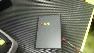
Oxygen sensor tester
This circuit basically tells you how your O2 sensor is functioning. Whether or not it is receiving the right signals for the ever-changing air/fuel ratio mixture.
It has an input from the sensor that varies, and depending on the input voltage given from the sensor, it uses operational amplifiers to give various signals. We use LEDs to display the different outcomes as a result of the varied input signal from the sensor (O2 sensor). Red LED displays a rich Fuel/Air ratio mixture, Green displays a lean mixture and yellow is Lambda1 (correct ratio mixture).
When the car is running lean the oxygen sensor puts out a very low voltage. This would make the input at pin12 lower than the 0.23v at pin13 and in turn allows pin14 to ground out through pin11. The green LED will be on.
When the car is running rich the oxygen sensor produces a higher voltage. In this case, it will be higher than 0.63v at pin6. The red LED will then be grounded through pin11, and be turned on.
To find;
R2 = [Vs - Vd (led1) - Vd (d2)] / A
= (12v - 1.8v -0.7v) / 9.5mA (minimum current needed to flow through the LEDs)
= 9.5v / 0.0095A
= 1000ohm
= 1k/ohm resistor
R3 = [Vs - Vd (led5) - Vd (d2) - Vd (d4)] / A
= (12v - 1.8v - 0.7v - 0.7v) / 9.5mA
= 8.8v / 0.0095A
= 926.315ohm
= 1k/ohm resistor
R4 = [Vs - Vd (led6) - Vd (d2)] / A
Components:
= (12v - 1.8v -0.7v) / 9.5mA
= 9.5v / 0.0095A
= 1000ohm
= 1k/ohm resistor
R5 = [Vs - Vd (d2) - Vz (zener diode)] / A
= (12v - 0.7v - 9.1v) / 5.6mA (current needed flow through the zener diode)
= 2.2v / 0.0056A
= 392.857ohm
= 390ohm resistor
R6 = 10k/ohm
= 10000ohm (as given)
To find R7 & R8, we must firstly find the current in the circuit they are on, so;
Voltage drop across R6 = the voltage going IN (Vin) minus the voltage coming OUT (Vout);
= 9.1v (Vin) - 0.63v (Vout)
= 8.47v
Now we divide the voltage drop into the resistance as ohms laws requires and;
Current across R6 = 8.47v / 10000ohm
= 0.000847A
= 0.847mA
This determines current across R7 & R8, and from here we can calculate their resistance values by dividing their voltage drops (Vin - Vout) into the current. So;
R7 = Vd (Vin - Vout) / A
= (0.23v - 0v) / 0.847mA
= 0.23v / 0.000847A
= 271.546ohm
= 270ohm resistor
R8 = Vd (Vin - Vout) / A
= (0.63v - 0.23v) / 0.847mA
= 0.4v / 0.000847A
= 472.25ohm
= 470ohm resistor
Components needed:
1 x 14 pin out op-amp
3 x 1N4001 diodes
3 x LEDs (red, yellow and green)
1 x Zener diode (9.1v)
3 x 1 k/ohm resistors
1 x 10 k/ohm resistor
1 x 390 ohm resistor
1 x 470 ohm resistor
1 x 270 ohm resistor
2 x 0.1 uF capacitor
Below is a couple links to videos of my oxygen sensor tester in operation. You can see how, as the throttle opens it gives a rich signal and as the throttle is released a lean signal is given.
Below is a couple links to videos of my oxygen sensor tester in operation. You can see how, as the throttle opens it gives a rich signal and as the throttle is released a lean signal is given.
http://www.youtube.com/watch?v=X8-9xLdYL5s
 |
| The oxygen sensor tester displaying a rich mixture |
 |
| The oxygen sensor tester displaying a lean mixture |
Under normal conditions the tester will fluctuate between the rich and lean mixture signalling LEDs. This is because of the ECU receiving these same signals and is adjusting the amount of fuel added to the air-fuel mixture constantly. This in turn keeps the emissions relativly close to Lambda1 which is good.
A fault in the circuit is giving a zero volt (0v) reading before and after each LED.
This means that the fault is somewhere before all the LEDs. Back tracking and testing components reveals 12v is available before the diode D2. Although after the diode available voltage is zero.
At first glance, I could not visually see anything abnormal. But slighty playing with diode revealed an open circuit. Cracks between the solder and the track had stopped current from flowing in through the first component to the rest of the circuit.
Repairing this gives us correct voltage drops across the LEDs, and the rest of the circuit again.
To do this experiment again would allow me to be a bit more delicate with my soldering to prevent shorts and/or open circuits.

No comments:
Post a Comment