Circuit Board #1
Construct a circuit, simulating an injector circuit
This board simulates two 5V signals sent to two individual fuel injectors (LEDs are used for simulation purposes) in a circuit. We use a function generator to produce the ECU simulating pulse of 5 volts through the base of the transistors.
This board simulates two 5V signals sent to two individual fuel injectors (LEDs are used for simulation purposes) in a circuit. We use a function generator to produce the ECU simulating pulse of 5 volts through the base of the transistors.
 |
| Injector Circuit wiring diagram |
To Calculate resistance needed;
Datasheet info:
BC547:
max Ic = 100mA (0.1A) & Ib = 5mA (.005A)
min Ic = 10mA (0.01A) & Ib = 0.5mA (.0005A)
This also gives us Beta (B). Ic / Ib = B:
0.1(100mA) / 0.005(5mA) = 20
0.01(10mA) / 0.0005(0.5mA) = 20
Datasheet info:
BC547:
max Ic = 100mA (0.1A) & Ib = 5mA (.005A)
min Ic = 10mA (0.01A) & Ib = 0.5mA (.0005A)
This also gives us Beta (B). Ic / Ib = B:
0.1(100mA) / 0.005(5mA) = 20
0.01(10mA) / 0.0005(0.5mA) = 20
Datasheets are nessesary to calculate the values of the resistors (r13, r14, r15 & r16). They indicate that the LEDs needs a minimum of 20mA (0.02A) in its circuit to operate. The Collector side of the Transistor has a minimum of 10mA and a maximum constant current rating of 100mA (0.1A).
So iv decided the current needs to be safely between 20mA (to enable the LED to operate) and 100mA. 60mA (0.060A) is good.
Therefor;
B (beta) = 20
Ic = 60mA
And if, Ib = Ic / B
= 0.060A / 20
= 0.003A
Then that would mean,
Ib = 3mA
Components:
2x NPN type transistors
2x 1 k/ohm resistors
2x 470 ohm resistors
2x LEDs
Using Lochmaster demo allows us to create a base design to work with. Its gives us a range of components to choose from. It also allows you to add labels and measurements to each of your components and/or symbols.
Using this base design we construct a breadboard sample. This will be our prototype.

R14 (red) = 9.69V
R15 (white) = 10.05V
R13 (red) = 4.67V
 |
| Lochmaster design (reverse) |
 |
| Lochmaster design (top) |
Using Lochmaster demo allows us to create a base design to work with. Its gives us a range of components to choose from. It also allows you to add labels and measurements to each of your components and/or symbols.
Using this base design we construct a breadboard sample. This will be our prototype.

 |
Injector Circuit complete (top) |
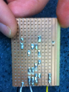 |
| Injector Circuit complete (reverse) |
After construction of the board, all looks visually sound and works as it should. But, voltage drop results across components is a very important part of Autotronics and is a great skill to know and understand. It reveals operating conditions and/or malfunctions beyond visual inspection.
Voltage drop across;
LED #1 (red) = 2.2V - functioning normally
LED #2 (white) = 1.9V - functioning normallyR14 (red) = 9.69V
R15 (white) = 10.05V
R16 (white) = 4.67V
The measurements are taken with a seperate power source of 5V, connected up to both the base inputs of the two transistors. Also having their own seperate earth hooked up back through both emitters.
These voltage drop readings indicate the LEDs are all functioning normally,
and there are no signs of a short, an open circuit or any other malfunction.
No comments:
Post a Comment