Experiment #3
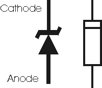
Zener diode
Constructing a electrical circuit on a breadboard, using 2 x resistors (both 100ohm), a Zener Diode (Zd) and a 12v supply voltage (Vs). Run one resistor (Rl) in parallel with the Zener Diode (Zd) and the second resistor (R) in series with both the Zener diode and the other resistor (Rl).
The Zener Voltage (Vz) is equal to the voltage drop across the Zener Diode. The voltage drop across the Zener is 4.99v, therefor the Zener Voltage is 4.99v.
If you were to lower the supply voltage (Vs) to 10v, the voltage drop decreases to 4.78v, therefor the Zener Voltage decreases to 4.78v.
Also if the voltage were to increase to 15v, the voltage drop across the zener increases to 5.13v, therefor Zener Voltage increases to 5.13v. Zener diodes are used to regulate voltage and supply a steady current.
Reversing the polarity of a Zener Diode changes its function. Zener voltage becomes 0.8v and it functions as a normal diode would.


No comments:
Post a Comment